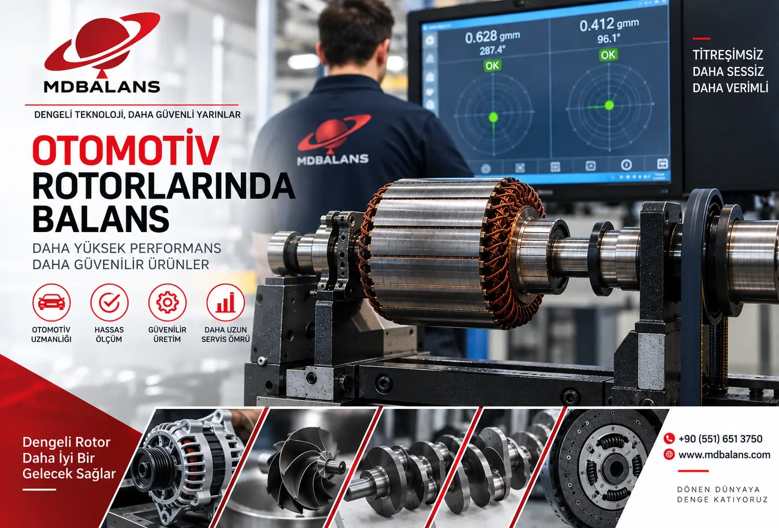
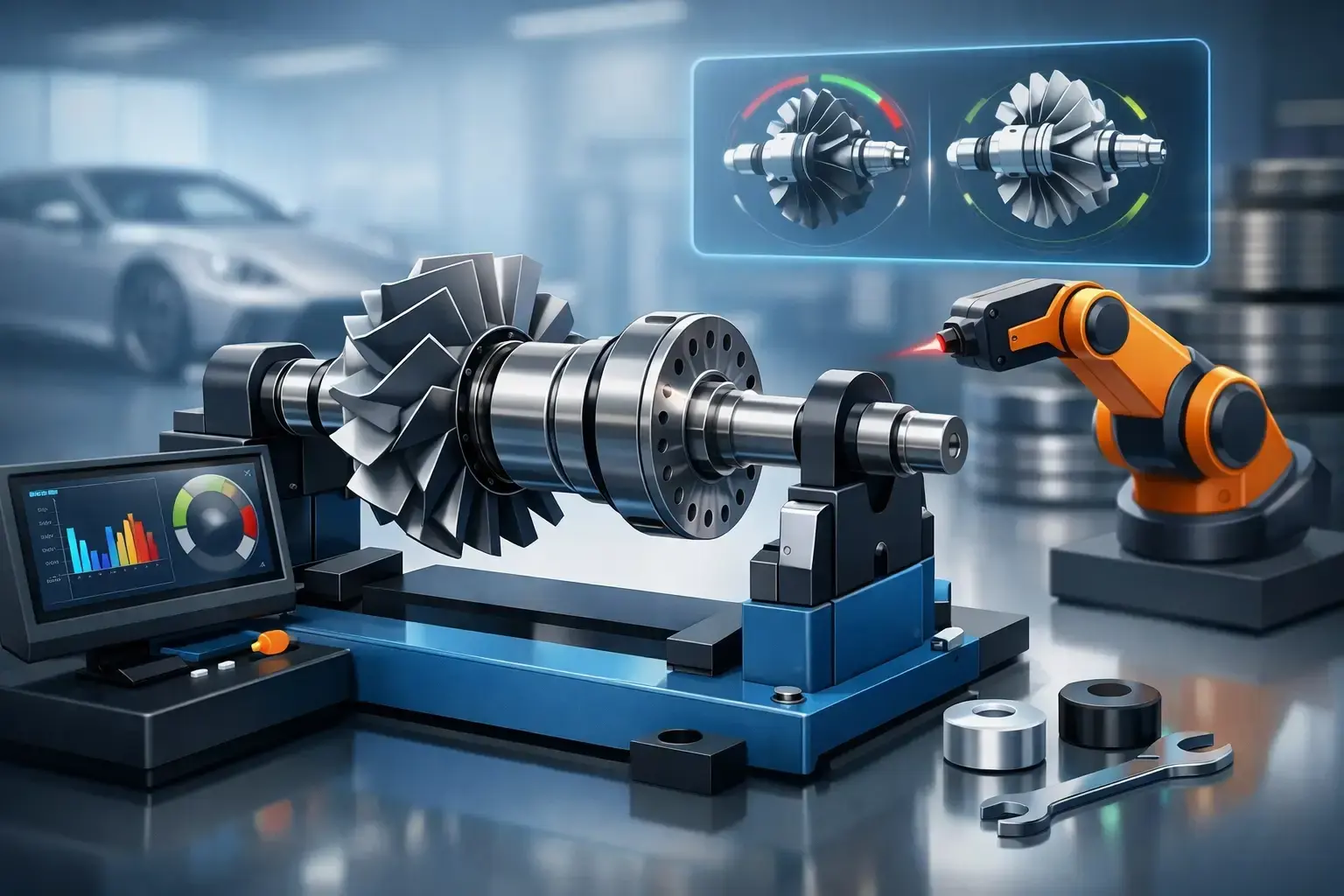
A few grams of imbalance in an electric drive rotor can result in noticeable vibration, bearing load, and noise at high speeds. Therefore, an automotive rotor balancing guide should address not only the selection of measurement equipment but also the mounting method, target quality grade, correction process, and final inspection discipline. The correct balancing approach helps maintain consistent part quality on the production line while reducing the risks of premature wear and warranty claims in the field.
Why is balancing critical for automotive rotors?
Rotors used in the automotive industry do not represent a single product group. Electric motor rotors, alternator rotors, turbocharger shafts, fan assemblies, pump impellers, crankshafts, clutch components, and other rotating parts in drive systems have different masses, geometries, and rotational speeds. Nevertheless, they share the same fundamental risk: when the axis of rotation and the center of mass do not coincide, centrifugal force is generated.
This force increases as rotational speed rises. A small imbalance that can be tolerated at low speed may reach unacceptable levels in a high-speed electric motor or turbo application. The result is not limited to noticeable vibration. Bearing life may be shortened, bearing housings may wear, connections may loosen, and NVH targets may deteriorate. Especially in mass production, the same defect affecting a large number of parts can rapidly increase quality costs.
Balancing also contributes directly to production efficiency. A balanced rotor behaves more consistently at test stations and reduces post-assembly noise complaints and rework rates. However, targeting the lowest possible imbalance value for every rotor is not economical. The correct objective is to achieve a tolerance appropriate to the component's operating conditions in a reliable and repeatable manner.
Automotive rotor balancing guide: first define the component
The balancing process begins before the component is mounted on the machine. The rotor's mass, operating speed, length-to-diameter ratio, bearing points, mounting references, and final application must be determined. For example, a short, disc-shaped impeller and a long electric motor rotor are not evaluated using the same method. Two-plane imbalance becomes more significant in long rotors, and the influence of the mounting fixture also becomes more critical.
During the initial assessment, the following questions should be clarified: At what maximum speed will the component operate, will balancing be performed on the individual component or as an assembled unit, and where are the permitted areas for material removal or addition? It should also be considered whether the rotor will undergo subsequent processes such as coating, magnet assembly, welding, press fitting, or final machining. A component that is correctly balanced before these processes may become unbalanced again during a subsequent operation.
When defining quality targets, the ISO 21940 approach can be used as a reference. However, the selected quality grade should not be determined solely from the standard's table. The rotor's actual speed, applied load, comfort requirements, bearing design, and customer specifications should be evaluated together. An unnecessarily tight tolerance on a low-speed pump impeller may increase cycle time. On a high-speed drive rotor or turbo component, however, a loose tolerance may put product performance at risk.
Distinguish between static and dynamic imbalance
In static imbalance, the heavy point of the rotor tends to continuously move toward the same side during rotation. Single-plane correction may be sufficient for many short rotors. In dynamic imbalance, however, the mass distribution at the two ends of the rotor differs and creates a moment around the axis. In this case, measurement and correction in two planes are required.
A component appearing statically balanced does not mean that it will operate dynamically balanced at high speed. Therefore, as operating speed increases, rotor length increases, or NVH requirements become more stringent, dynamic balancing should be preferred. Especially in electric vehicle drive systems, the expectation of quiet operation makes balancing quality a part of acoustic performance as well as mechanical durability.
How should the correct balancing machine and mounting system be selected?
Horizontal balancing machines are a common solution for shaft-type rotors supported between two bearings. Crankshafts, electric motor rotors, alternator rotors, and similar components can be measured precisely on horizontal systems with the appropriate bearing distance and drive arrangement. Vertical balancing machines, on the other hand, can provide advantages in terms of cycle time and operator ergonomics for discs, fans, impellers, and short-rotor components.
Machine selection should not be based solely on maximum rotor weight. Minimum measurable imbalance, achievable rotational speed, rotor diameter, bearing distance, drive type, automation level, and measurement system repeatability should be evaluated together. In mass production, automatic loading, marking, material removal, or weight addition stations help keep cycle times under control. For prototypes, maintenance applications, or highly diverse products, flexible fixturing and rapid program changes may be more valuable.
The mounting fixture is an unseen determining factor in measurement. Dirt on a tapered surface, incorrect centering, a loose chuck, or a worn adapter can produce misleading results that appear to be rotor imbalance. The balance of the fixture itself should be checked, and the component's actual production reference surfaces should be preserved as much as possible. If a rotor is centered from its flange in the vehicle, forcing it to use a different reference during testing may disrupt measurement correlation.
Conditions to be checked before measurement
Even if the balancing machine is calibrated, environmental and component conditions affect the result. Burrs, oil, chips, welding spatter, or loose components on the rotor should be removed. Measurements performed on welded or press-fitted assemblies without verifying mechanical integrity are not reliable.
The difference between the rotor's operating temperature and balancing temperature should also be considered. In precision applications where thermal expansion is significant, it should be evaluated whether measurements taken in the cold state accurately represent operating conditions. In permanent-magnet electric motor rotors, magnet positioning, adhesive distribution, and the concentricity of the protective sleeve also directly affect mass distribution.
Correction process: minimum intervention, maximum repeatability
After measurement by the balancing machine, the system indicates the magnitude and angular position of the imbalance. Correction can be performed by controlled material removal from the heavy point, adding weight at a specified position, applying welding, or using an adjustment element suitable for the design. The preferred method varies depending on rotor material, safety requirements, and production volume.
Material removal is a permanent and clean method for steel rotors and certain cast components. However, the structural strength of the correction area should not be weakened, and critical surfaces should not be damaged. Adding weight is suitable for thin-walled components or parts where material removal is undesirable; however, it must be verified that the added component will remain securely attached at high rotational speeds. In correction by welding, the effect of heat input on deformation and material properties should not be overlooked.
Controlled correction followed by repeated measurement is more reliable than making a large adjustment in a single operation. Especially for rotors with tight tolerances, the accuracy of the correction angle should be monitored along with the residual imbalance value after correction. Operator experience is important; however, in mass production, results should not depend on the individual operator. Programmed recipes, correction limits, automatic guidance, and recording systems strengthen process stability.
Final inspection and traceability are part of production
A successful balancing process does not end when an acceptable value appears on the screen. Re-mounting and checking the same rotor demonstrates repeatability, particularly for critical components. If a significant difference occurs after re-mounting, the problem may lie in the fixture, centering, or process discipline rather than in the rotor itself.
Production records should include rotor type, serial number, initial imbalance, correction amount, residual imbalance, measurement planes, operator, and date. These data are necessary not only for responding to customer quality requirements but also for identifying process trends. Consistently higher initial imbalance during a particular shift may be an early indication of issues such as machining tool wear, deviation in welding parameters, or changes in supplied components.
Periodic machine calibration, maintenance planning, and software verification are also integral parts of traceability. In a precision measurement system, neglected maintenance can gradually weaken the reliability of a well-designed process. MDBALANS evaluates machine selection, refurbishment, calibration, and technical service approaches for automotive and general industrial applications according to this need for continuity.
Bringing the rotor's actual operating conditions, production method, and quality target together within the same measurement strategy transforms balancing from merely a final inspection step. Such an approach makes it possible to control vibration problems on the production line rather than investigating them after the product has entered service.