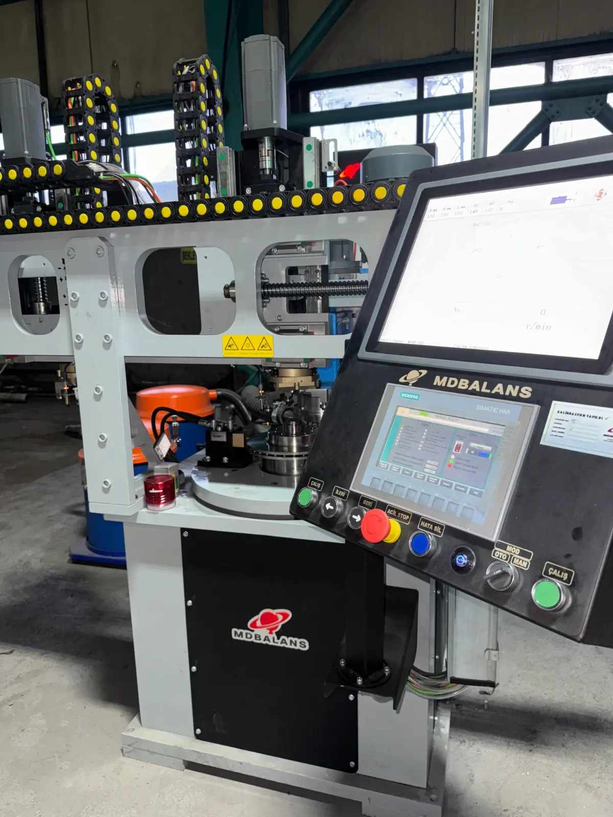
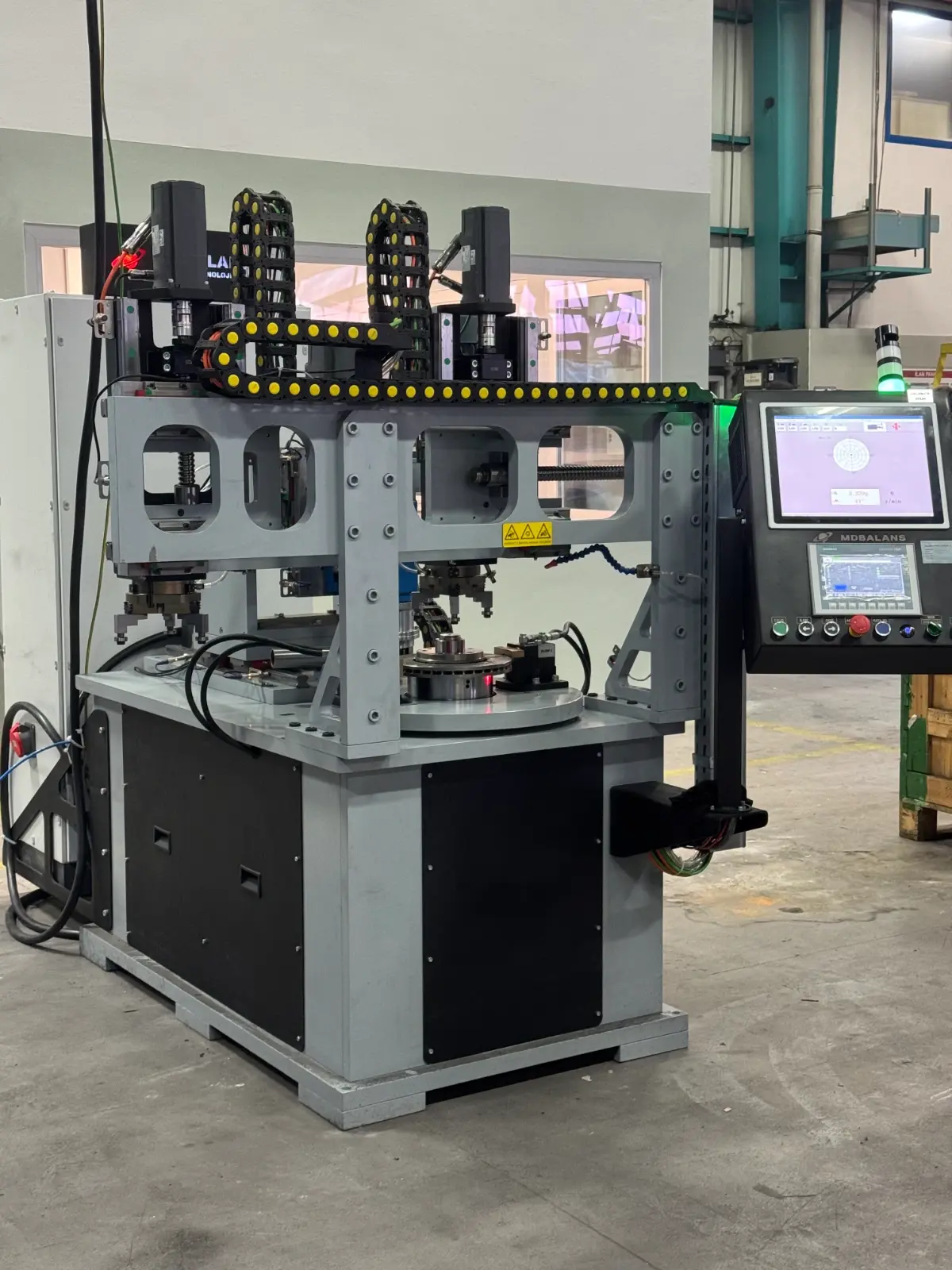
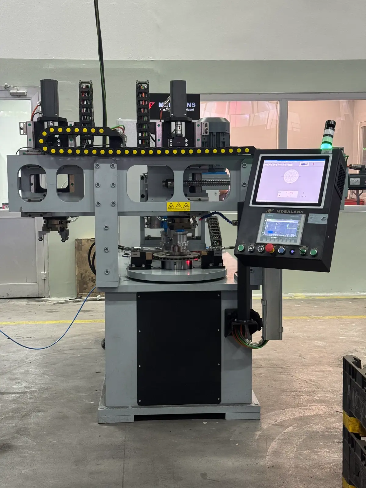
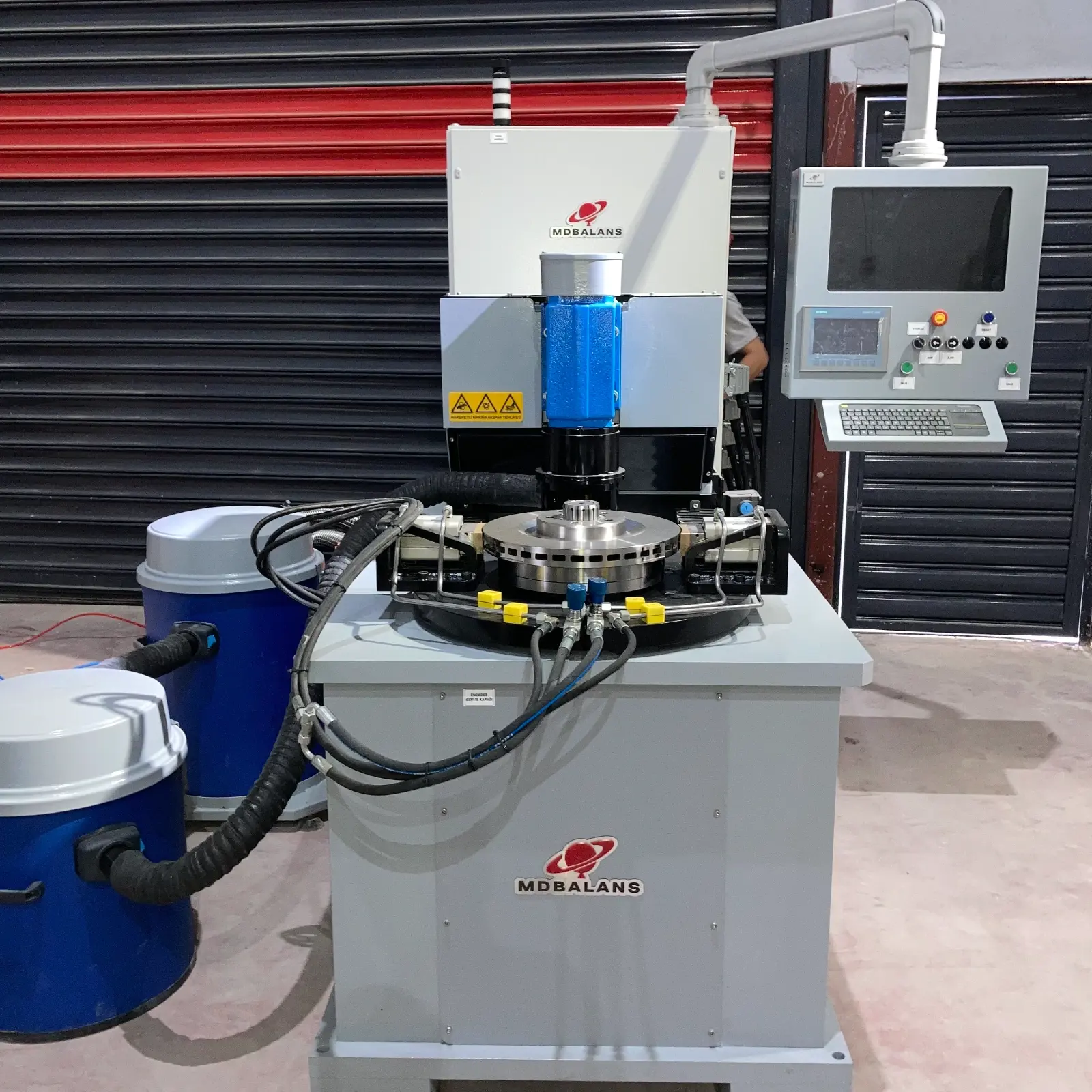
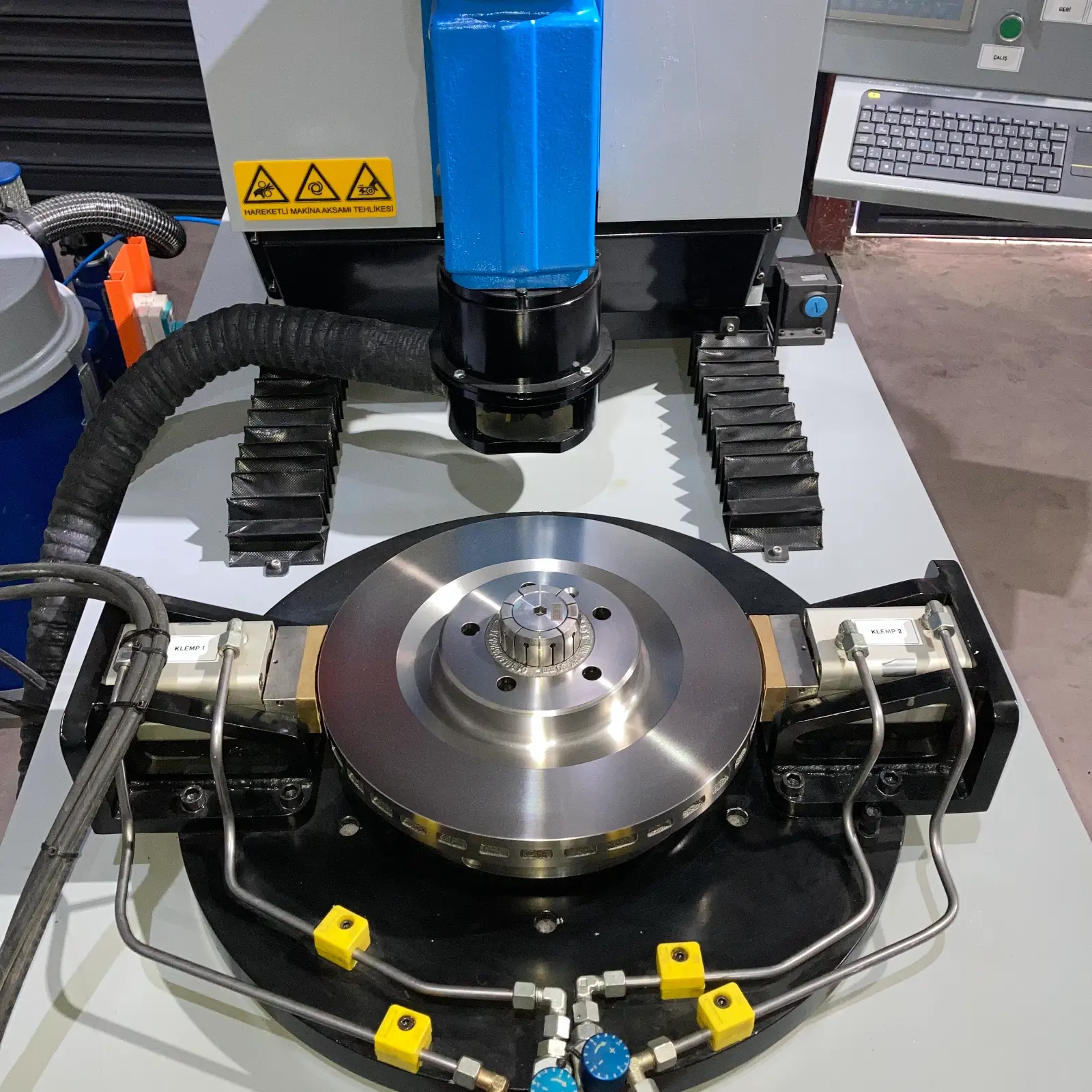
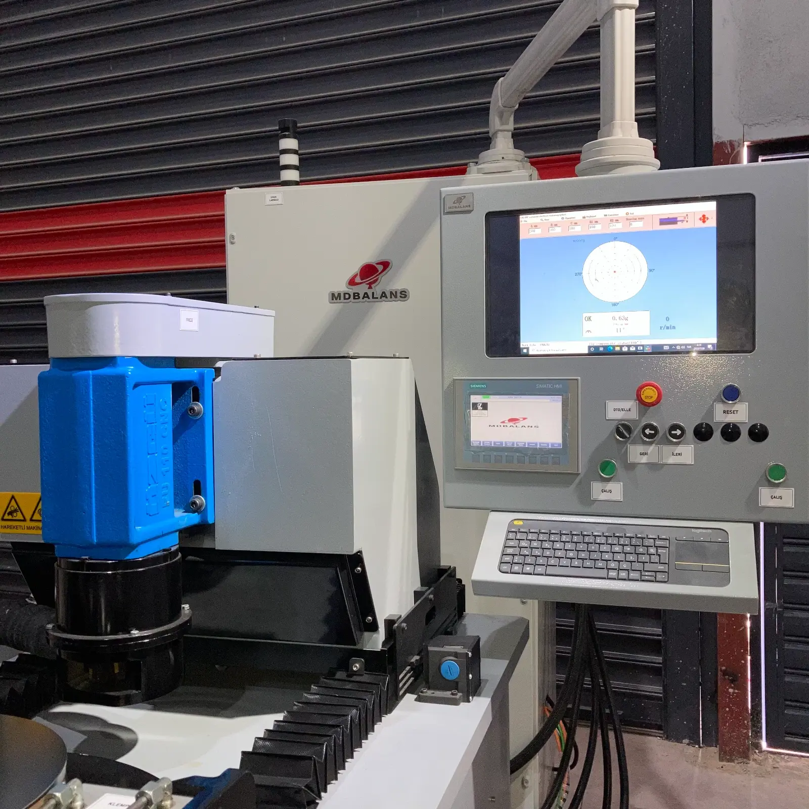
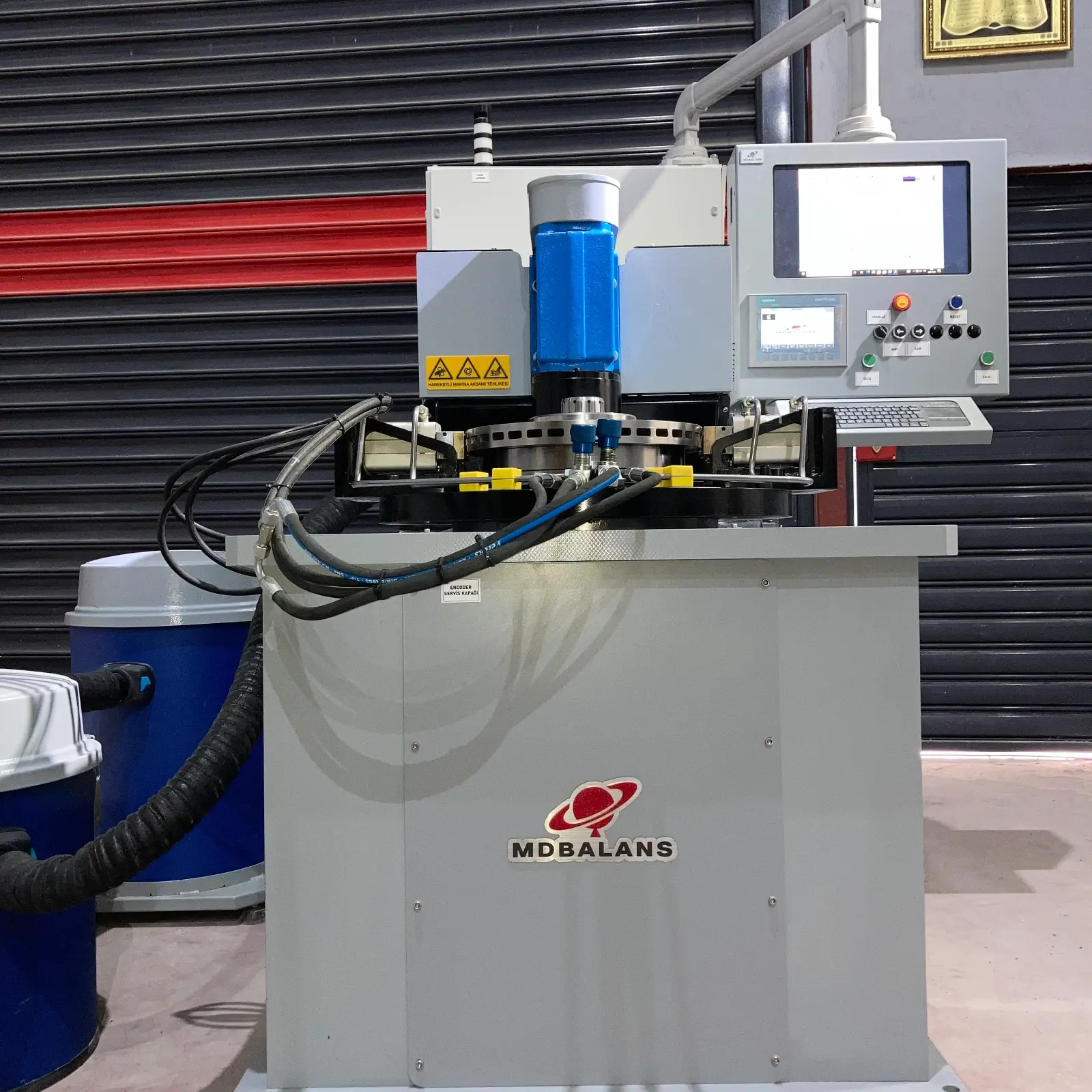
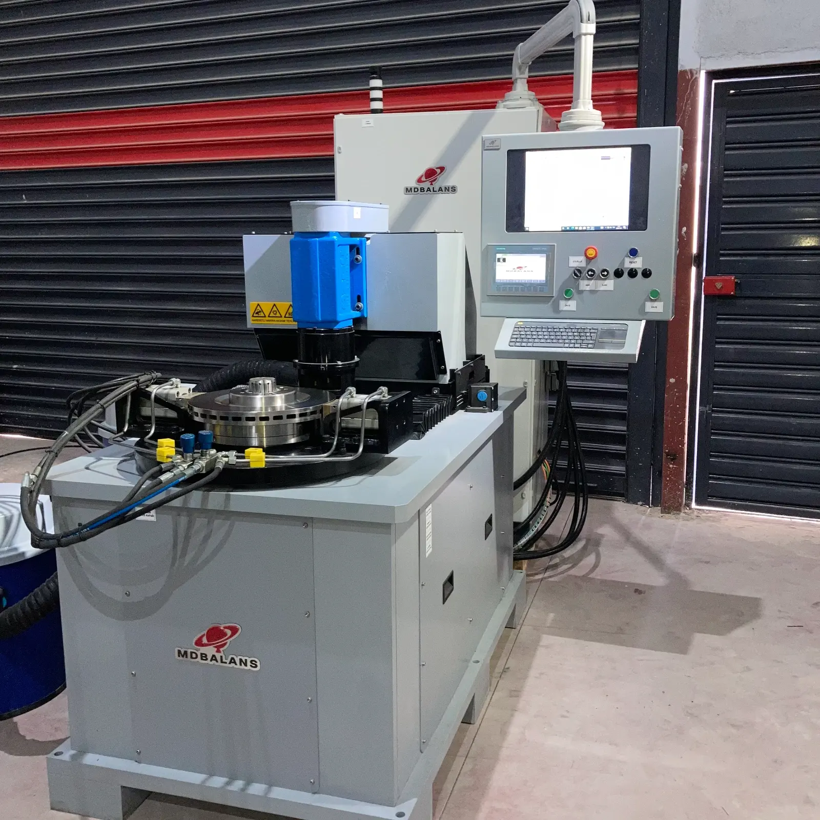
MD100-DFO is a belt-driven, automatically loaded vertical balancing machine. These machines are recommended for balancing brake discs. It is capable of balancing static parts. With its automatic balancing function, the milling system calculates the required hole and depth and automatically brings the balancing value within the specified tolerances.
1- Measurement Plane
The machine is equipped with a hard pedestal. It has a fixed servo-controlled belt drive. The part is clamped using a special chuck according to the hub diameter through a diaphragm system.
2- Drilling System
1 drilling system with a 5.5 kW motor, independently controlled by servo motors on the Z and X axes. It can perform channel cutting up to 40 mm. A milling cutter can be connected, and the system is equipped with a dust extraction attachment.
3- Dust Extraction System
The 3 kW blower system collects chips in its container. The system is portable and movable.
4- Hydraulic System
During the drilling operation, the rotor is securely locked with the help of two jaw pistons.
5- Safety Cage System
The system automatically opens and closes using linear guides and pistons. With the PILZ safety system, the machine cannot operate while the cover is open. A switch monitors whether the cover is closed.
6- Robot System
The linear guide system has an X-axis controlled by a servo motor. Part handling is performed using two independently controlled Z axes.
Drive type: Belt-driven
Maximum capacity: 100 kg
Minimum capacity: 2 kg
Maximum rotor diameter on the plane: 600 mm
Minimum rotor diameter on the plane: 150 mm
Number of planes: 1 hard bearing - 1 servo-controlled
Balancing quality ratio: 95%
Minimum unbalance: ISO 21940 balance quality G grades
Power supply: 400 V, 50 Hz, 3-phase
Motor power (belt drive): 3 kW
Maximum rotational speed: 830 rpm
Minimum rotational speed: 200 rpm
Air pressure: 6 bar
Measurement time: 60 sec.
Safety system: Automatic cover with safety switch
Part loading/unloading: Manual (by operator)
Operating system: Microsoft Windows
Display: 15” industrial display
Remote technical support: TeamViewer / AnyDesk
Storage: 256 GB SSD
Passwords: Operator, supervisor, admin
Communication channels: Ethernet, Wi-Fi and USB
Balancing units: Grmm - Grcm - Gr
Electronic compensation: Weight control
Connection adapter compensation: Resets the adapter balance
Rotor database: Data records with fast search functionality
Measurement results display: Digital / Polar
Factory rotor calibration: Balancing is performed by entering the measurement values
Standard calibration process: Manual calibration, calibration weight entry
Report printing: Exports the final balancing value in Excel format. USB options are also available.
Automatic measurement backup: Automatically saves every test measurement.
Balancing Quality Parameter
The MDBalans balancing software includes an integrated permanent unbalance calculation module compliant with the ISO 21940 standard. You can easily determine the appropriate balancing quality grade (G) for your rotor type using the explanations provided in the relevant sections. Tolerance values are calculated automatically.
Report
The balancing machine software automatically records all balancing operations in Excel format. It automatically records the initial high unbalance value and the balancing value after the balancing operation. Excel files can be copied using a USB device.
Operation Steps
Calibration
The calibration process is performed using a master part and a certified calibration weight. The master part will be calibrated using the customer's part. Once gram calibration has been performed for the selected part in the software, no further calibration is required unless a model change (different part) is made. When a model change is made for a different part, calibration is required for accurate and precise measurement.
Occupational Safety
The enclosed safety cage prevents the operator from contacting the part during rotation. The safety system is controlled by PILZ relays and switches. Emergency stops and the door system comply with occupational health and safety standards. ADMIN, SUPERVISOR and OPERATOR passwords are provided through the automation screen for user access restriction. Critical interventions can only be performed by authorized users.
MES System Data Transfer (OPTIONAL)
The balancing machine automation system includes the necessary infrastructure for customers to retrieve required data and transfer it to their own MES systems. The automation system of the balancing machine is SIEMENS-based. Within this infrastructure, the values that customers can retrieve from the machine are updated after each production cycle in a datablock with predefined addresses. The customer's existing MES system can read the required information from this datablock, store it on its own server, and process the data. Machine information can be shared with the MES system.

