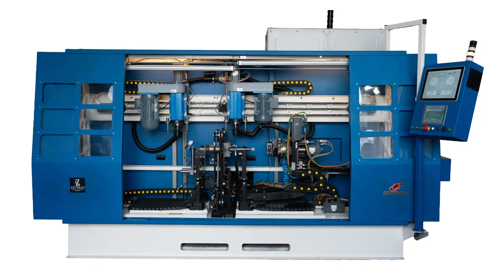
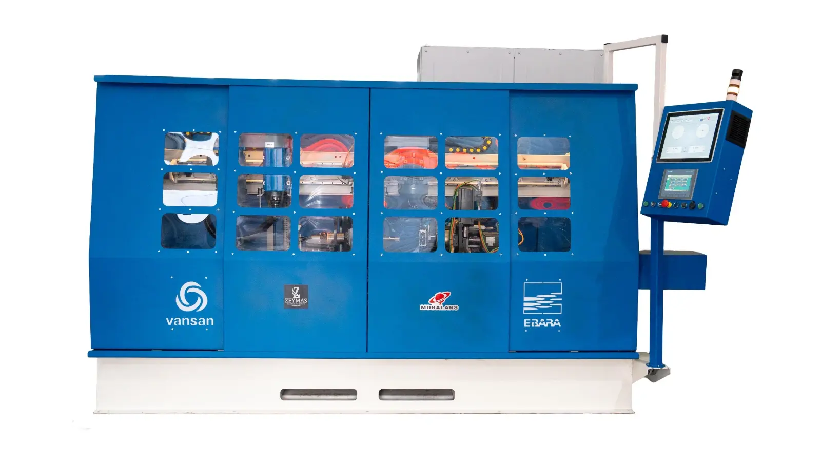
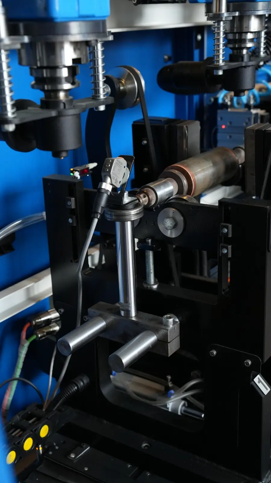
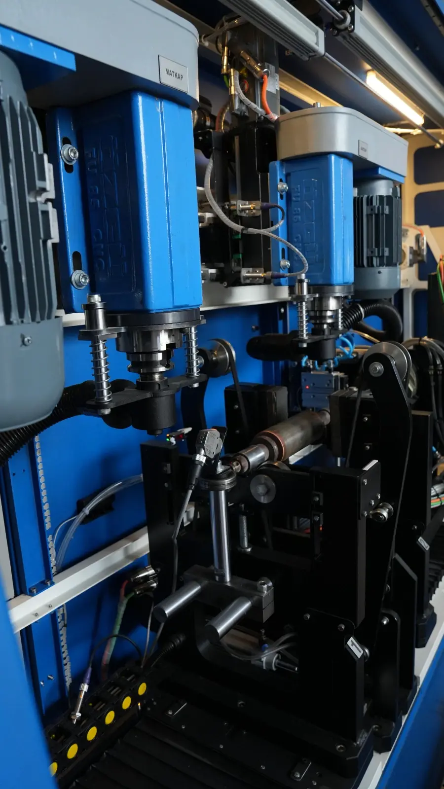
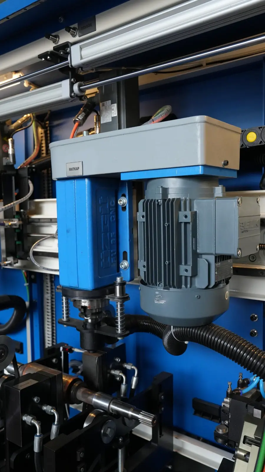
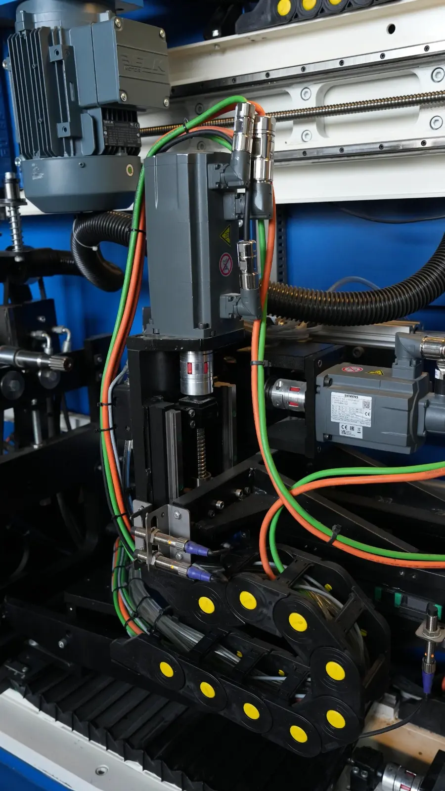
The MD500-OYM is a belt-driven, 10-axis horizontal balancing machine designed for precision balancing of cylindrical rotors. The system supports both static and dynamic balancing applications and combines measurement with automatic correction. Its integrated drilling system calculates the required hole position and drilling depth automatically, allowing the rotor to be brought within the defined balancing tolerance.
1- Measurement Plane
The machine features a rigid hard-pedestal measurement structure. Its fixed servo-controlled belt drive provides stable and controlled rotor rotation throughout the balancing cycle.
2- Automatic Drilling System
The machine is equipped with two independent drilling units. The 2.2 kW drilling systems are servo-controlled on the Z-X axes and can perform drilling operations up to 12 mm. A milling tool can also be connected when required. A dust extraction attachment can be used to control chips generated during machining.
3- Chip and Dust Extraction System
A 3 kW blower system collects chips generated during the correction process and transfers them to the collection chamber. The mobile and movable design allows the extraction system to be positioned according to the requirements of the working area.
4- Hydraulic Rotor Clamping System
Two jaw pistons are used to secure the rotor during drilling or milling operations. The hydraulic clamping system helps prevent rotor movement and provides stable positioning during the balancing correction process.
5- Automatic Safety Enclosure
The safety enclosure operates automatically using a linear guide and piston mechanism. The PILZ safety system prevents machine operation while the enclosure is open. Safety switches monitor whether the doors are securely closed before the balancing cycle starts.
Technical Specifications
Drive type: Belt-driven
Maximum component capacity: 500 kg
Minimum component capacity: 2 kg
Maximum rotor diameter: 350 mm
Minimum rotor diameter: 50 mm
Balancing planes: 2 hard feet, 2 servo-controlled
Balancing quality rate: 95%
Balancing quality standard: ISO 21940 G grades
Power supply: 400V, 50 Hz, 3 phase
Belt drive motor power: 1 kW
Maximum rotational speed: 1400 rpm
Minimum rotational speed: 200 rpm
Air pressure: 6 bar
Measurement time: 60 sec.
Safety system: Automatic enclosure with safety switches
Component loading/unloading: Manual, operator controlled
Operating system: Microsoft Windows
Display: 15” industrial display
Remote technical support: TeamViewer / AnyDesk
Storage: 256 GB SSD
User authorization: Operator, Supervisor, Admin
Communication interfaces: Ethernet, Wi-Fi and USB
Balancing units: grmm, grcm, gr
Electronic compensation: Weight control
Adapter compensation: Adapter balancing reset
Rotor database: Fast-search data recording system
Measurement display: Digital / Polar
Calibration: Manual calibration and weight identification
Reporting: Excel format recording and output
Automatic backup: Each measurement result is automatically stored.
Balancing Quality Parameter
The MDBalans software includes an integrated residual unbalance calculation module compliant with the ISO 21940 standard. The appropriate balancing quality grade (G grade) can be determined according to the rotor type and application. Based on the selected quality level, the software automatically calculates the required tolerance values and presents them to the operator.
Automatic Reporting
The balancing machine software automatically records completed balancing operations in Excel format. The initial unbalance value and the value obtained after the balancing correction process are stored together. This allows the operator to compare measurement results and maintain production quality records. The generated Excel files can be transferred to external storage through the USB interface.
Operating Sequence
When the system is ready and the safety doors are open, a component loading signal is sent to the robot. The robot loads the component into the machine and sends a loading-completed signal before moving back to the safe zone. The safety doors then close and the rotor clamping system centers the component.
The measurement cycle starts and the rotor unbalance values are measured. The system automatically positions the unbalance correction point under the drilling unit. Hydraulic clamps secure the rotor, after which the required drilling or milling operation is performed. All moving components are then returned to their safe positions before the final balancing measurement is carried out.
If the final balancing value is within the specified tolerance, the system sends a component unloading signal to the robot. The safety doors open, the robot removes the component and sends the unloading confirmation. The balancing machine then returns to its ready position for the next cycle.
Calibration Process
Calibration is performed using a master component and a certified calibration weight. The master component can be selected according to the customer's actual production component. Once gram calibration has been completed for a specific component in the software, recalibration is generally not required as long as the same component model continues to be processed. When switching to a different component model, calibration should be performed again to maintain accurate and precise measurement results.
Safety and User Authorization
The enclosed safety system prevents the operator from accessing the working area while the rotor is rotating. Machine safety functions are monitored using PILZ safety relays and switches. Emergency stop functions and safety doors are designed to support applicable occupational safety requirements.
User access can be managed through Admin, Supervisor and Operator authorization levels on the automation interface. Critical settings and interventions can be restricted to authorized personnel.
MES System Data Transfer (Optional)
The automation infrastructure of the MD500-OYM can be prepared for data exchange with the customer's MES system. The machine automation system uses a SIEMENS-based infrastructure.
After each production cycle, measurement and machine data can be updated within defined data blocks. The customer's MES software can read the required information from these data areas, store it on its own server and analyze the production data. This enables balancing results to be integrated into production tracking and quality management systems.

